Hi all, trouble with the electrics I'm afraid. Here's the story, my project bike is a 1991 and should be running a 3 wire power valve servo, only problem is the loom has been changed at some point and has connectors for the 5 wire servo, I find this out after buying the 3 wire type.
The 3 wire servo has a built in controller and the pin out is brown+, black-, bullet connector signal.
Now my issue is, the wiring pin outs I've discovered on here so far all indicate the black/yellow wire is the signal wire to the pv, however there is no black/yellow on the cdi (3rm-30) or on the loom. I've checked here for pinouts too:
The black/yellow is in fact the signal wire on the servo, still no idea which wire that hooks up to on the CDI though.
I can probably test the wires coming from the CDI if anyone knows what the power valve should be getting, it's got to be either a variable voltage or variable pulses.
__________________
A poke in the eye's better than a kick in the sack.
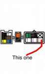
Ok, I've got a wire on the loom near where the servo should be, it's not black/yellow as expected for the servos signal wire but does have the bullet connector. I've traced the wire back and it does go to the cdi, the diagram bellow shows where.
Does anyone know if this is where the pv servo signal wire should come out the cdi?
The diagram is looking face on at the plug coming from the cdi, as though you could plug the loom straight into it if that makes sense.
Hope someone can help now, getting desperate here lol
Clearly I have an unusual CDI (3RM-30), my wiring loom works with my CDI and the wire colours seem to follow between the loom and CDI therefor you'd imaging I probably have the correct loom to go with my unusual CDI. I just need to get my three wire servo running which should be easy enough, i just need to know where the servos signal wire is, is the bullet connector always the servos signal wire anyone? Anyone at all know where the signal wire comes out the CDI? I need to know physically where the black/yellow wire is in your CDI's plug. Thanks
__________________
A poke in the eye's better than a kick in the sack.
so your rare cdi that is suppose to be good runs from a loom that runs a 5 wire servo ? then I would think if the cdi and loom are so good then you should stick with a 5 wire servo I see no gain in wireing in a 3 wire .
some of us rate the 3 wire servo on as it fits to the better older cdi .
That's right, I have an unrestricted CDI running on a 5 wire loom. I've uncovered a few things whilst researching this but still don't understand everything fully. One thing I can say for certain is the 3 wire servo is no better and no worse than the 5 wire, it functions in the same way when on the bike, the difference is the 3 wire has an inbuilt controller, that's why it only needs 3 wires, the 5 wire version only contains the motor and a variable resistor. I've also discovered my CDI is basically a 3RM-20 open CDI, that was good news as another forum member thought his 3RM-30 may have been restricted. Here's what I still don't know, if the CDI can control the 5 wire servo why was the 3 wire used initially? Or do the 5 wire bikes have an extra pv control module somewhere? The reason I'd like to fit the 3 wire valve is I have it, I certainly wouldn't want to buy anything if this setup will work. Thanks for the interest MDK, looks like it's only you and i here though lol
-- Edited by Periwinkle Ramstanza on Friday 2nd of May 2014 11:13:42 AM
__________________
A poke in the eye's better than a kick in the sack.
Thanks for the interest MDK, looks like it's only you and i here though lol
-- Edited by Periwinkle Ramstanza on Friday 2nd of May 2014 11:13:42 AM
no lol they will all be taking a look in but some times do not comment if they are unsure ..where as I just comment tregardless if I know or not lol.
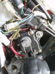
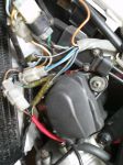
not sure if this helps any ..just taken some pics of mine 1989 3 wire servo only the black and yellow go to cdi the other two brown - black go in to the loom . maybe of no help but still ya never know maybe a usefull pic for some googlers
-- Edited by MDK on Friday 2nd of May 2014 01:56:59 PM
Thanks for the effort mate, can you see where that black/yellow wire goes into the CDI? If you look at my diagram above you'll see where I think it might go, obviously the colour code is different on your wiring but the location of the pin could be the same.
__________________
A poke in the eye's better than a kick in the sack.