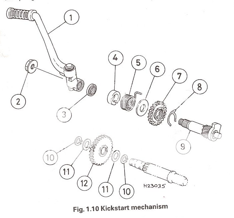
DT125R ARCHIVE

Members Login
Username 
 
Password 
    Remember Me  
Post Info TOPIC: DT125RE/X Kick Start Conversion Tutorial


Guru

Status: Offline
Posts: 7569
Date:
DT125RE/X Kick Start Conversion Tutorial
Permalink Closed


DTRE/X Kick Start Conversion


This is a tutorial for future reference for anyone who is thinking of or is going to carry out a kick start conversion for their DT125RE. This may also help if you are going to dismantle the clutch to replace/inspect or repair. It may also help if you wish to replace the kick start or idle gear.


Required parts for installation:

Kick Start Mechanism

Idle Gear

2 X Circlips

2 X Thrust washers

Kick start Lever

Nut  (outer nut to secure lever)

Oil Seal

If you cannot find the Kick start complete or are looking for parts then here is a list of the parts that comprise of the kick start mechanism:

1.       Kickstart Shaft

2.       Friction Clip

3.       Kickstart Pinion

4.       Washer

5.       Return Spring

6.       Spring Guide


SSSee Haynes Manual diagram from setup of the kickstart mechaism


Description:


You may find that you may require a tool to take the nut off the clutch as the hardest part is removing the clutch to insert the Idle gear. It helps to have an assistant at this point however I was able to remove this bolt on my own using a homemade device.


NORFE recommends the use of this the clutch removal tool:

Ebay:

Search-

CLUTCH HOLDING TOOL


Or click link:


http://www.ebay.co.uk/itm/CLUTCH-HOLDING-TOOL-SUZUKI-GSF-GSX-GSXR-VS-VX-VZ-/270845565000?pt=UK_Motorcycle_Parts&hash=item3f0fa75848#ht_500wt_1054


I would say that this can be a fairly easy job to do yourself however this is a guide for interest and help should you need it and I am not responsible for your actions.


 Description: DT125RE


To start!

Put the bike into sixth gear

Remove fairing covering expansion bottle

Remove seat

Remove  petrol tank

Remove exhaust

To enable the gearbox casing to be removed it helps to remove the rear brake pedal. To do this first remove the return spring. This can be done by inserting a flat head screw driver and carefully leveraging the spring out of place. Remove the bolt holding the brake pedal in place. This bolt should have a split pin on the other side. This will need to be removed. From beneath the master cylinder remove the dowel holding it in place. This is secured by a split pin.


If you are having trouble removing any bolts or items then it may help to first heat the item up by using a heat gun. If a heat gun is not available then you could try using a hair dryer. I highly recommend using an impact driver to remove stubborn bolts.


The brake pedal can now be removed.

Drain the coolant by unscrewing the drainage bolt and undoing the radiator cap. Detatch radiator hose from radiator tank. Attached the hose is a metal pipe that runs from the radiator to the water pump. Unscrew this as this will help when reinstalling the gearbox case. Examine picture to find cooland sump:


Description: Cooland Sump


Coolandpipe.jpg 


Drain the gear box oil by unscrewing the oil drainage sump

Loosen all case fasteners then remove all screws. Its a good idea to replace these bolts for stainless steel ones as I managed to round most mine off!

Heres possible a link to the bolts I used:

http://www.ebay.co.uk/itm/150629092204?ssPageName=STRK:MEWNX:IT&_trksid=p3984.m1497.l2649


Should that link no longer work then here is the item description to use in eBay.


280 Qty STAINLESS ALLEN BOLTS KIT YAMAHA DT 125 R


This came at a price of around £10 ( Which I  thought was a bargain!). They make the bike look better as well IMO.

Description: Bolts


Description: Bolts2


Description: Bolt3


Remove the gearbox casing. If this is being stubborn try tapping its sides with a hammer whilst still pulling back on the casing. Avoid using a flat blade as leverage as this may damage the casing itself. If the closing isnt completely flush then oil may seep through when reassembled. Once the casing has been removed the gasket may be taken off. You can use this gasket as a template to create your new one or discard it as you may have purchased one.


Evenly unscrew the clutch springs in a diagonal pattern. DO NOT UNFASTEN ONE WITHOUT UNFASTENING THE OTHERS. Like I said evenly unscrew each clutch spring in a diagonal pattern. It may help to leave the push rod as it is. Remove the clutch pressure plate. Be careful when removing the push rod as a small ball bearing may fall out which is required when reassembly. If it does fall out then re-grease it and return it to the centre of the clutch. Grease up the push rod.  Remove the clutch plates and friction plates HOWEVER MAKE SURE THE ORDER REMAINS THE SAME UPON REFITTING!!!  You should note that the washer is bent up to the nut. This is normal and will need to be hammered down before the nut can be removed.  By using a socket and ratchet remove the nut. The longer the ratchet the better Leverage is your friend.


Description: Clutch


This nut can be VERY STUBBORN and some improvisation may be required for it to come off. The problem is is that the clutch basket spins as you try to remove the bolt. By using a piece of long metal you could drill through it and secure it to the clutch pillars and add a counter force to it to allow you to release the nut. Or the tool can be used.


Once this nut has been removed the clutch basket can come off. It may seem stubborn as the cogs it sits between are curved. By rotating the basket and pulling you can remove the basket. The kick start mechanism can now be installed. By examining the photos install the kick start mechanism. The cog should lift as it rotates so it can engage with the idle gear.


Description: Nut


An exposed beam next to the kick Start mechanism can now be reached. Install the first circlip to this beam, followed by; a washer, the idle gear, the second washer and the final circlip. The idle gear should sit firmly on the beam. Should there be any play side to side I have been told that it shouldnt matter as there wont be a load on the cog when the engines running so it shouldnt be too much trouble. The clutch basket should be inspected for any burs or signs of wear. The friction plates should be examined for any signs of blueing. This will indicate overheating inside the clutch. Also inspect the steel ball to ensure there are no flat spots. Inspect the push rods to make sure they are not bent.


See diagram:

Description:


Description: Idle


Description: Kick


Description: Spring Reset


See haynes diagram:


Description:


Description:


Once satisfied that parts can now be installed reinstall the clutch basket using the same method you used to dismantle it. If you took the washers off then install thrust washer first followed by the splined one. See diagram below if unsure:


Description:


Make sure that the idle gear connects with the primary gear and that the kick start engages the idle gear. Once that is satisfactory you may now start to install the clutch plates. When doing so inspect the clutch plates to ensure there is plenty of life in them. If not its best to replace the set.


When installing the clutch plates notice how one clutch plate has a larger internal diameter than the others. This clutch plate must be installed second, followed by the damper ring and then the friction plate. Also upon installation notice how the plain plates have a cutaway in them. This makes them unbalanced and the clutch will need to be rebalanced should it to work correctly. They should be equally spaced out by 60o  so that  it is balanced. Apparently this is done to reduce clutch noise!


A list of how the clutch should be assembled for reference:
Friction plate,
Plain plate (metal) 12 o'clock,
Friction plate with damper ring,
Plain plate (metal) 2 o'clock,
Friction plate,
Plain plate (metal) 4 o'clock,
Friction plate,
Plain plate (metal) 6 o'clock,
Friction plate,
Plain plate (metal) 8 o'clock,
Friction plate,
Plain plate (metal) 10 o'clock,
Friction plate,


Or see the Haynes manual picture:


Description: Clutch setup


When installing the clutch springs ensure that they are with the handbook specified relax length. If not then the whole lot should be replace. When installing them do as you did when removing them and tighten them equally in diagonals until all are tight. Ensure that the push rod is secured in its place and make sure that the punched mark on the pressure plate sits above punched mark on the basket. This punched mark may also be an arrow.  See Haynes diagram if unsure:


Description:


Go to the casing. Where it says Kick starter that seal must be removed. By using a socket, pressure can be applied to its reversed side and hammered out of place. Install the new oil seal. Replace the gearbox case to the bike ensuring that the alignment dowels are in place and that the new gasket is fitted. Ensure it lines up correctly and fasten up to the engine ensuring not to over tighten and cross thread or snap the bolts. If the oil pipe has been removed then this will need to be bled again.


Install the clutch lever and bolt and the kick start should now be working!


KickstartComplete2.jpg


Remember to top up the gearbox oil and to refill the coolant. It's a good idea to leave the bike ticking over with the radiator cap off to allow water to be pumped through the system and then add more water as it circulates around the engine.


If there are any problems with this tutorial or corrections that need to be made or rewording of any sort then please leave a comment so I can correct it.


I hope this helped thanks!

Sources:

Haynes Manual, Personal Experience, XGINCATX, NORFE


-- Edited by Calum122 on Sunday 11th of March 2012 07:29:39 PM


-- Edited by Calum122 on Sunday 18th of March 2012 07:48:15 PM


-- Edited by Calum122 on Sunday 18th of March 2012 08:42:42 PM


-- Edited by Calum122 on Sunday 18th of March 2012 08:43:33 PM


-- Edited by Calum122 on Sunday 18th of March 2012 08:46:02 PM


-- Edited by Calum122 on Sunday 18th of March 2012 08:46:27 PM

__________________

Always Originate, Never Pirate!

The Leviathan Project


Guru

Status: Offline
Posts: 607
Date:
DT125RE Kick Start Conversion Tutorial
Permalink Closed


Very nice guide
Skimmed over alot since I could do it all blindfolded lol
But when it comes to re assembling the clutch I'd say this

Here's the order they go in:
Friction plate,
Plain plate (metal) 12 o'clock,
Friction plate with damper ring,
Plain plate (metal) 2 o'clock,
Friction plate,
Plain plate (metal) 4 o'clock,
Friction plate,
Plain plate (metal) 6 o'clock,
Friction plate,
Plain plate (metal) 8 o'clock,
Friction plate,
Plain plate (metal) 10 o'clock,
Friction plate,

Oh and in regards to taking the badass clutch nut off:
I think the best way is to put the bike into gear before you take the side casing off, dismantle until you get to the nut, then get the longest bar possible (leverage is your friend) then get someone else to sit on the bike and hold the back brake in, if the bike still insists on moving then jam something between the rear wheel and the swinging arm

EDIT: Oh and some of them black and white photo's from the haynes would pretty much perfect it wink
Especially the clutch overview one showing all the parts, Might be in the service guide so you could just print screen it off that rather then taking a grainy picture of the haynes evileye


-- Edited by xGINCATx on Sunday 11th of March 2012 11:17:51 AM

__________________

Sig


DTR Trusted Engine Builder

Status: Offline
Posts: 1723
Date:
Permalink Closed

or just invest in a tool best 20 quid ull ever spend iv had this about 10 years u can take the clutch nut off in about 30 seconds

http://www.ebay.co.uk/itm/CLUTCH-HOLDING-TOOL-SUZUKI-GSF-GSX-GSXR-VS-VX-VZ-/270845565000?pt=UK_Motorcycle_Parts&hash=item3f0fa75848#ht_500wt_1054


__________________


Guru

Status: Offline
Posts: 7569
Date:
Permalink Closed

Thank you!

And I know I should know this but FFS!


I went:

Clutch Plate

Plain Plate

Clutch Plate

Plain Plate

Damper Ring


GAY! That might explain why it isn't working that well.


However I swear it isn't that clear in the Haynes!


__________________

Always Originate, Never Pirate!

The Leviathan Project


Guru

Status: Offline
Posts: 7569
Date:
Permalink Closed

Alterations have been made. That should improve it.

__________________

Always Originate, Never Pirate!

The Leviathan Project


Guru

Status: Offline
Posts: 7569
Date:
Permalink Closed

Ok so it hasn't saved!

Gay


__________________

Always Originate, Never Pirate!

The Leviathan Project


Guru

Status: Offline
Posts: 7569
Date:
Permalink Closed

Done. Any ideas are welcome.

__________________

Always Originate, Never Pirate!

The Leviathan Project


Guru

Status: Offline
Posts: 607
Date:
Permalink Closed

"Also upon installation notice how the friction plates have a cutaway in them."
It's the plain plates with the notch sticking out of them,
I'm 99.9% positive it doesn't matter how you put the friction plates in (other then ensuring the one with the damper ring is the second one to go on)
I still need to read it all, just keep reading bits lol,
I'll try and read it fully and let you know, but good job so far, Just needs to be stickied and our posts underneath deleting and it locking smile

EDIT:

Title might aswell include DTX aswell as DTRE owners since the engine is the same and both lack a kickstart!
Oh and if I remember correctly, for me to take the side casing off I had to remove a radiator hose at the opposite side of the casing, it connected to a metal pipe that went around to the waterpump, that might need adding in the guide
Oh and after replacing the coolant leave the radiator cap off and rev the bike for a while as it gets rid of any air locks in the cooling system, replace coolant as required, do this until no air bubbles are seen coming out of the radiator cap


-- Edited by xGINCATx on Monday 12th of March 2012 11:26:38 AM

__________________

Sig

Page 1 of 1  sorted by
Quick Reply

Please log in to post quick replies.

Tweet this page Post to Digg Post to Del.icio.us


Create your own FREE Forum
Report Abuse
Powered by ActiveBoard